International Journal of Mining, Materials, and Metallurgical Engineering (IJMMME)
ISSN: 2562-4571

Volume 2 - Year 2016 - Pages 8-19
DOI: TBA
Computational Analysis of Inter-Material Mixing and Weld-Flaw Formation during Dissimilar-Filler-Metal Friction Stir Welding (FSW)
M. Grujicic, R. Yavari, S. Ramaswami, J. S. Snipes, R. Galgalikar
Clemson University, Department of Mechanical Engineering,
Clemson, SC 29634, USA
gmica@clemson.edu
Abstract - Friction stir welding (FSW) butt-joining involving the use of a dissimilar filler-metal insert between the retreating and advancing portions of the workpiece is investigated computationally using a Combined Eulerian-Lagrangian (CEL) finite element analysis (FEA). The FEA employed is of a two-way thermo-mechanical character (i.e. frictional-sliding/plastic-work dissipation was taken to act as a heat source in the energy conservation equation), while temperature is allowed to affect mechanical aspects of the model through temperature-dependent material properties. Within the analysis, the workpiece and the filler-metal insert are treated as different materials within the Eulerian sub-domain, while the tool was treated as a conventional Lagrangian sub-domain. The use of the CEL formulation within the workpiece insert helped avoid numerical difficulties associated with excessive Lagrangian element distortion. The emphasis of the computational analysis was placed on the understanding of the inter-material mixing and weld-flaw formation during a dissimilar-material FSW process. The results obtained revealed that, in order to obtain flaw-free FSW joints with properly mixed filler- and base-materials, process parameters including the location of the tool relative to the centerline of the weld must be selected judiciously.
Keywords: Dissimilar-filler-metal Friction Stir Welding, Process Modeling by Finite Element Method.
© Copyright 2016 Authors - This is an Open Access article published under the Creative Commons Attribution License terms. Unrestricted use, distribution, and reproduction in any medium are permitted, provided the original work is properly cited.
Date Received: 2014-11-21
Date Accepted: 2016-03-24
Date Published: 2016-06-07
1. Introduction
1.1. The Basics of Friction Stir Welding
Friction stir welding (FSW) is a solid-state material joining process within which a non-consumable hard-material welding tool is rotated and advanced to generate (via frictional-sliding and plastic-work dissipation) sufficient heat, a prerequisite for successful welding, in the workpiece material surrounding the tool/workpiece interface. A detailed description/analysis of the FSW process could be found in the seminal work by W. M. Thomas and co-workers [1, 2] and, hence, only a brief overview of a few aspects of the FSW process, most relevant to the present work, will be given in the remainder of this subsection.
The main FSW process parameters which affect both the weld quality and the process efficiency are: (a) rotational velocity of the tool; (b) traverse velocity of the tool; (c) tool-plunge depth; (d) tool tilt-angle; and (e) tool design/material.
FSW normally involves complex interactions and competition between various mass and heat transport phenomena [3, 4], plastic deformation and damage/fracture mechanisms [5] and microstructure evolution processes [6-10]. Consequently, the material microstructure (and mechanical properties) in the weld region are highly complex and spatially diverse. Metallographic examinations of the FSW joints (e.g. [11]) typically reveal the existence of the following four well-defined weld zones (not counting the unaffected/base-metal zone, which is far enough from the weld so that material microstructure/properties are not altered by the joining process): (a) heat-affected zone (HAZ); (b) thermo-mechanically affected zone (TMAZ); (c) weld nugget (also referred to as the stir zone); and (d) flow arm.
1.2. Use of Filler-Metals in Welding
In many non-FSW welding technologies (e.g. fusion welding), a filler metal is used to help fill the groove/gap separating the two portions of the workpiece being joined [12-13]. Experience gained over many years of welding practice has clearly demonstrated that, if properly selected and handled, filler metal can maximize weld efficiency (i.e. the ratio of the weld minimum strength and the base-metal average strength) and, sometimes, make it greater than 1.0. Since sub-1.0 welding efficiencies are generally encountered in the case of FSW, it is logical to ask if the use of filler metal within the FSW can have similar beneficial effects as in the case of the fusion-welding processes. However, due to mismatches in the mechanical properties of the dissimilar filler- and base-metals, FSW involving dissimilar-filler-metals may pose additional challenges (and even compromise the feasibility of the joining process). These challenges will be addressed computationally in the present work [14].
1.3. Prior Experimental Work on Dissimilar-Material FSW
A review of the public-domain literature carried out as part of the present work revealed a number of experimental studies dealing with dissimilar-material FSW. In the remainder of this subsection, a brief overview is provided of a few of these studies which are deemed most relevant to the present work.
Dinaharan et al. [15] investigated the effect of various FSW process parameters, including material location (advancing vs. retreating side), on the material flow, defect formation, microstructure and spatial distribution and mechanical properties within (microstructurally) dissimilar-material joints involving AA 6061 aluminum alloys having as-cast and as-rolled microstructural states. The results obtained clearly revealed that the material flow, joint structural soundness, microstructure and properties are all sensitive functions of the FSW process parameters, including material (advancing-vs.-retreating side) location. Specifically, it was shown that the best mechanical properties in the weld are obtained when the as-cast AA 6061 is placed on the advancing side and when the rotational speed of the weld tool is in a critical range which ensures complete mixing of the two materials within the stir region without excessive heat generation.
Deghani et al. [16] carried out a comprehensive experimental investigation of the effect of various FSW process parameters on the defect content, intermetallic volume fraction, and mechanical properties of dissimilar-material joints involving AA 5186 aluminum alloy and low-carbon steel. The experimental investigation established the presence of a relatively narrow process window within which the joints were defect-free and had a low intermetallics content, and the mechanical properties were at least 90% of those found in the base AA 5186.
Ghosh et al. [17] investigated experimentally the feasibility of dissimilar-material FSW of cast, Si-rich AA 356.0-T6 and wrought, Mg-Si AA 6061-T6 aluminum alloys, and the resulting microstructural properties of the FSW joint. The results obtained revealed that the joint mechanical properties are improved by reducing the aluminum-matrix grain size and the Si-rich precipitate size, and that the welding speed affects the matrix-grain size and the precipitate size in opposite ways, so that the best mechanical properties of the FSW joints are obtained at an intermediate value of the weld-tool traverse speed.
Guo et al. [18] conducted a thorough experimental study of the effect of various FSW process parameters on material flow, microstructure, microhardness distribution and tensile properties of the dissimilar-material joints involving AA 6061 and AA 7075 aluminum alloys. The study established that the two aluminum alloys can be successfully FSWed, and that the structural soundness and mechanical properties of the weld are fairly sensitive functions of the process parameters. In addition, it was demonstrated that, due to the previously mentioned asymmetry of the FSW joint, the placement of a given alloy on the advancing or retreating side of the weld can have a significant effect on the material flow as well as on the resulting weld microstructure and properties.
Liu et al. [19] carried out a detailed microstructural and mechanical-property characterization of the dissimilar-material FSW joint involving AA 6061-T6 aluminum alloy and transformation-induced plasticity (TRIP) steel. The work encompassed a comprehensive analysis of the fragmentation of the steel within the joint into micron-sized particles, conversion of these Fe-rich particles into Fe-Al intermetallic particles and the (beneficial) role of the Fe-rich and Fe-Al particles in enhancing tensile-strength properties of the FSW joint. In addition, an attempt was made to predict the as-welded microstructure for a given set of FSW process parameters by carrying out a real-time measurement of the spindle torque and tool-traversing force, as well as the surface temperature.
1.4. Prior Computational Work on Dissimilar-Material FSW
A review of the public-domain literature carried out as part of the present work did not reveal any computational study addressing the problem of dissimilar-material FSW. However, as will be demonstrated in the present work, most of the aspects of the single-material FSW process modeling will be retained, with little or no modification, when dissimilar-material FSW process is being modeled. Consequently, in the remainder of this subsection, a brief overview will be provided of the main recent developments in the computational modeling of the single-material FSW process.
Extending the original work of Zhang and co-workers [20, 21], Grujicic and co-workers [14-15, 22-31] advanced the FSW process modeling and its application to the welding of thick all-metal armor structures, so that the modeling can address the following critical issues:
- the effect of various FSW process parameters (e.g. tool geometry and material, rotational and traverse speeds of the tool, tool tilt angle and plunge depth, thickness of the workpiece, contact pressure) on the material flow, microstructure evolution, residual-stress development and defect formation within FSW joints;
- establishment of the functional relationships between the material microstructure and defect content within different portions of the FSW joint and the local mechanical properties (e.g. hardness, strength, toughness, ductility); and
- correlation between the spatial distributions of the material microstructure and properties within the weld, and the ballistic-protection performance of the weld with respect to the key armor-defeat mechanisms such as petaling, ductile hole enlargement, plugging and spalling.
In the last couple of years, the FSW computational work has focused on issues such as process optimization (e.g. [32]), non-butt-FSW joints (e.g. [33]) and tool/workpiece slip/stick contact conditions (e.g. [34]).
1.5. Main Objectives
The main objective of the present work is to carry out a finite-element analysis (FEA) of the FSW process involving a dissimilar filler metal, in order to reveal the associated base-/filler-metal mixing, as well as the potential for the development of weld flaws (yielding structurally inferior welds). In order to address the potential problems accompanying a numerical analysis of the FSW process which arise from excessive distortions of the Lagrangian-type elements, a combined Eulerian/Lagrangian FEA [35] is employed in the present work.
2. Computational Modeling and Analysis
As mentioned earlier, due to the potential numerical problems associated with extensive element distortion, the conventional displacement-based Lagrangian finite element formulation was not used to model the FSW process in the present work. Instead, the so-called Combined Eulerian-Lagrangian (CEL) fully-coupled thermo-mechanical analysis [35] was employed. It should be recognized, however, that the pure Lagrangian and the CEL analyses share many features. Since details regarding the use of the conventional Lagrangian FEA in the FSW process simulation can be found in our prior work (e.g. [29-31]), only the features specific to the CEL analysis will be covered here.
2.1. Geometrical Model
The computational domain used consists of two separate sub-domains, one of an Eulerian-type and the other of a Lagrangian-type. The Eulerian sub-domain (used to model the advancing and retreating sides of the workpiece and the filler-metal insert) is of a rectangular-parallelepiped shape with the dimensions of Lx × Ly × Lz = 100 mm × 50 mm × 8 mm. The Cartesian-coordinate axes are selected in the following way: the x-axis is aligned with the direction of welding, y-axis runs in the workpiece-width direction, while the z-axis is in the through-the-thickness direction. The middle rectangular-parallelepiped portion (having dimensions Lx, 0.08Ly, Lz) of the Eulerian sub-domain is used to place the filler-metal insert. The remaining two parts of the sub-domain are used to accommodate the advancing and retreating sides of the workpiece. As far as the FSW tool is concerned, it is modeled as a Lagrangian sub-domain having a tapered threaded pin and a cylindrical shoulder with an upright truncated conical under-cut. Schematics of the geometrical models for the two sub-domains are depicted in Figure 1. It should be noted that in this figure, for clarity, the tool is shown in the retracted position.
2.2. Meshed Model
The Eulerian sub-domain is discretized using a fixed mesh based on 8-node brick elements with a characteristic edge length of 0.8 mm. The tool, treated as a Lagrangian component, is discretized using 4-node tetrahedron continuum elements. The Eulerian sub-domain typically contained 88704 elements while the Lagrangian sub-domain contained 17660 elements.
2.3. Computational Algorithm
As mentioned earlier, a CEL-based finite element analysis of the dissimilar-material FSW process is developed in the present work. Within this analysis, the workpiece, including the filler-metal insert, is treated as an Eulerian sub-domain, the tool is treated as a Lagrangian sub-domain and the interaction between the two is treated using an Eulerian/Lagrangian contact ("fluid-structure interaction") algorithm. Within the Lagrangian sub-domain: (a) the mesh (nodes and elements) is attached to the associated material and moves and deforms with it; and (b) each element must be fully filled with a single material. On the other hand, within an Eulerian sub-domain: (i) the mesh is fixed in space and the material flows through it; (ii) elements are allowed to be partially filled and/or contain multiple materials; and (iii) since the material and the element boundaries do not generally coincide, a separate ("interface reconstruction") algorithm must be used to track the position of Eulerian-material boundaries [29].
Numerical solution of the governing equations in the Eulerian sub-domain within each time increment involves two separate steps: (a) the Lagrangian step within which the sub-domain is temporarily treated as being of a Lagrangian-type (i.e. nodes and elements are attached to and move/deform with the material); and (b) the "remap" step within which the distorted mesh is mapped onto the original Eulerian mesh and the accompanying material transport is computed and used to update the Eulerian-material states and inter-material boundaries.
As mentioned earlier, both plastic deformation and frictional sliding are treated as heat sources. To account for the fact that a small fraction of the plastic-deformation work is stored in the form of crystal defects, 95% of this work was assumed to be dissipated in the form of heat. As far as heat generation due to frictional sliding is concerned, it is assumed that its rate scales with the product of local interfacial shear stress and the sliding rate, and that 100% of this energy is dissipated in the form of heat.
The fully-coupled thermo-mechanical problem dealing with FSW is solved using an explicit solution algorithm implemented in ABAQUS/Explicit [35], a general-purpose finite element solver.
2.4. Initial Conditions
The Eulerian sub-domain is initially filled with the workpiece and the filler-metal materials by prescribing the appropriate material volume fractions to each Eulerian element. To enable the motions of the Eulerian materials at the workpiece upper surface in the outward normal direction (without material loss), one or more top Eulerian-element layers is initially left void. Furthermore, the Eulerian sub-domain is assumed to be initially stress-free and at rest. For the Lagrangian sub-domain, at the beginning of the analysis the tool is assigned a constant rotational velocity and a zero translational velocity. Lastly, both the Eulerian and Lagrangian sub-domains are assigned ambient-temperature initial conditions.
2.5. Boundary Conditions
For convenience, the longitudinal motion of the FSW tool is not considered explicitly. Instead, the longitudinal velocity of the tool is set to zero and the workpiece material is allowed to move through the Eulerian sub-domain in the x-direction with an overall longitudinal velocity equal to the negative of the desired tool translational velocity. This was accomplished through the use of the appropriate "in-flow" and "out-flow" velocity boundary conditions at the vertical xmin and xmax faces of the Eulerian sub-domains, the faces which are orthogonal to the welding direction. Thus, the Eulerian sub-domain displayed in Figure 1 does not represent the entire workpiece but rather a rectangular-parallelepiped region around the tool in the otherwise infinitely-long workpiece.
To simulate the effect of lateral clamping of the workpiece, "no-flow" boundary conditions are prescribed along the vertical ymin and ymax faces of the Eulerian sub-domain, the faces parallel to the welding direction. To mimic the role played by the workpiece rigid backing plate in preventing the flow of the workpiece material in the downward direction, zero-normal-velocity boundary conditions are applied over the bottom (zmin) surface of the Eulerian sub-domain. In accordance with the initial conditions prescribed to the top Eulerian-element layers, "out-flow" boundary conditions are prescribed over the top (zmax) surface of the Eulerian sub-domain.
As far as the thermal boundary conditions are concerned, standard convection boundary conditions are applied over free surfaces of the Eulerian and Lagrangian sub-domains, while enhanced convection boundary conditions are applied over the bottom face of the Eulerian sub-domain (to mimic the effect of enhanced heat extraction through the workpiece backing plate).
2.6. Tool/Workpiece/Filler-metal Contact Interactions
Interactions between the workpiece- and filler-metal-occupied Eulerian sub-domains, and the FSW tool Lagrangian sub-domain, are modeled using a penalty method and a modified Coulomb friction law [11]. As far as the thermal interaction between the two sub-domains is concerned, it requires specification of the partitioning of the heat generated by frictional sliding along the contacting surfaces of the two sub-domains. This partitioning is computed using the procedure described in Ref. [36]. According to this procedure, a ratio of the fractions of frictional-sliding-generated heat allotted to sub-domains 1 and 2 is given by:
where ![]() is the thermal
conductivity,
is the thermal
conductivity, ![]() is the mass density and
is the mass density and ![]() is the specific heat of the material in
question. It should be noted that the
is the specific heat of the material in
question. It should be noted that the ![]() sum
must be equal to the total heat generated during frictional sliding.
sum
must be equal to the total heat generated during frictional sliding.
In addition to the Eulerian-Lagrangian contacts, interactions (of a "sticky" character) also occur between different Eulerian materials, and are modeled using the approach described in Ref. [11].
2.7. Material Models
2.7.1. Tool Material
FSW
tools used for joining aluminum alloys are typically made of one of the
hot-working or high-speed steel grades (e.g. AISI H13 or AISI 350M). Due to
high strength of these steel grades at elevated temperatures, the tool
typically experiences very little plastic deformation during the FSW process [37,
38]. On the other hand, tool wear and loss of tool features after prolonged
use is frequently observed. Since an analysis of tool wear is beyond the scope
of the present work and the likelihood for plastic deformation of the tool is
very small, the tool material (AISI H13) is modeled as a mechanically-isotropic
linear-elastic material with a Young's Modulus of 210 GPa, a Poisson's ratio of
0.3 and density, ![]() , of 7825 kg/m3. The
thermal properties of this material which play an important role in
partitioning of frictional-sliding-induced heat at the tool/workpiece and
tool/filler-metal interfaces are assigned as: thermal conductivity, k = 28.5
W/m∙K and specific heat, cp = 475 J/kg∙K.
, of 7825 kg/m3. The
thermal properties of this material which play an important role in
partitioning of frictional-sliding-induced heat at the tool/workpiece and
tool/filler-metal interfaces are assigned as: thermal conductivity, k = 28.5
W/m∙K and specific heat, cp = 475 J/kg∙K.
2.7.2. Workpiece Material
Within the present work, FSW of AA5083-H321 workpiece is analyzed. AA5083 (nominal chemical composition: 4.5 wt% Mg, 0.25 wt% Cr, 0.75 wt% Mn) is an Mg/Mn solid-solution hardened alloy and, in addition, in its H321 temper state is cold work-hardened and stabilized (to obtain a needed level of ageing/over-ageing resistance). While Al6Mn precipitates are present in this alloy, due to the aforementioned stabilizing heat treatment, the precipitates located within the HAZ are generally found not to experience coarsening or dissolution. On the other hand, the precipitates located within the TMAZ, stir zone and flow arm are generally found to undergo major changes in their precipitate microstructure, with an accompanying loss of strength [11, 23, 24]. Consequently, it is the innermost portion of the FSW joint that typically possesses the most inferior mechanical properties within the weldment. To help mitigate the problem of inferior mechanical-properties within the FSW-joint, the use of chemically-similar, higher strength filler-metal aluminum alloys is explored in the present work.
The workpiece material (AA5083-H321) is assumed to be anisotropic, linear-elastic and strain-hardenable, strain-rate sensitive, thermally-softenable plastic material and is modeled using the Johnson-Cook material model [39]. A summary of the Johnson-Cook material model parameters (including the governing equation for the yield strength) and the elastic and thermal properties of AA5059-H131 can be found in Ref. [11].
Examination of the original Johnson-Cook material model reveals that a temperature change causes only a reversible change in material strength by affecting thermal activation of dislocation motion. In other words, the original Johnson-Cook model does not account for any permanent changes in the material microstructure and properties which may occur as a result of high-temperature exposure of the material. This approach is not fully justified in the case of FSW where, due to the attendant high temperatures, significant differences in the material microstructure and properties may exist between the base metal and the weld (as well as within different regions of the weld). To account for this additional effect of temperature, a modification of the strain hardening term within the original Johnson-Cook model was proposed in our prior work [30]. Specifically, the strain-hardening term is still assumed to be a parabolic function of equivalent plastic strain. However, the equivalent plastic strain is now defined as the sum of two terms: one (positive) which quantifies the contribution of plastic deformation to strain hardening and the other (negative) which accounts for strain softening induced by dynamic recrystallization. In other words, strain hardening is still assumed to be controlled by the density of (mobile) dislocations but the local value of this quantity is taken to be the result of a competition between dislocation-generating plastic deformation and dislocation annihilation associated with dynamic recrystallization. It should be noted that the first (positive) component of the equivalent plastic strain in the modified Johnson-Cook material model still quantifies the overall extent of inelastic deformation taking place at a given material point.
The
properties of AA5083-H321 used in the frictional sliding heat-partitioning
analysis are set as follows: ![]() = 2660 kg/m3,
k = 123 W/m∙K , cp = 982 J/kg∙K.
= 2660 kg/m3,
k = 123 W/m∙K , cp = 982 J/kg∙K.
2.7.3. Filler-metal Material
Following the filler-metal material selection principles described in the Introduction section, the filler-metal insert is assumed to be made of an aluminum alloy which: (a) is chemically similar (i.e. Al-Mg-Mn based) to AA5083; (b) is metallurgically similar to AA5083-H321, i.e. solid-solution strengthened, strain-hardened and (Al6Mn-precipitation) stabilized; and (c) possesses a higher level of strength than AA5083-H321. The following aluminum alloys have been identified and used as the filler-metal inserts: (i) AA5086-H321; and (ii) AA5456-H321. Since these filler-metal aluminum alloys are chemically and metallurgically compatible with AA5083-H321, their constitutive response is represented using the same material model (but with different parameterization [11]) as that adopted for AA5083-H321. Since mass density and thermal properties of the two filler-metal alloys and the base-metal alloy differ only slightly, they are all set to be equal.
3. Results and Discussion
The volume fractions of the two materials are monitored throughout the Eulerian computational sub-domain, in order to track material flow and base-/filler-metal mixing during FSW. That is, at the beginning of the simulation, the Eulerian computational sub-domain contained two (advancing and retreating workpiece sides) regions within which the volume fraction of the base-metal was 1.0 (while that of the filler-metal was 0.0), and one middle region within which the volume fraction of the filler-metal material was 1.0 (while that of the base-metal was 0.0). In the course of the FSW process, as a result of the stirring, the two materials became mixed and, within the major portion of the Eulerian computational sub-domain, the volume fractions of the two materials were neither 0.0 nor 1.0. When the sum of the volume fractions of the base- and filler-metal materials in a given element of the Eulerian computational sub-domain is not 1.0, the difference is made up by the void-material (indicating the formation of a pore-type flaw).
The main results obtained in the present work are presented and discussed in the remainder of this section. To better understand the challenges associated with dissimilar-filler-metal FSW, the case of same-filler-metal FSW is analyzed first.
3.1. Same Filler-Metal FSW (Baseline Case)
Based on our prior work, the following FSW process parameters have been chosen in this case: (a) tool rotation speed = 500 rpm; (b) tool traverse speed = 0.0025 m/sec; (c) tool tilt angle = 2.5° and (d) tool plunge depth = 0.0001 m.
It is generally observed that at the onset of the FSW process simulation, material flow/mixing fields pass through a transition state. Afterwards, these fields settle into a time-invariant steady state. An example of this transient-to-steady-state evolution for the volume fraction of the filler-metal material over the surfaces of the Eulerian computational sub-domain is depicted in Figures 2(a)-(d).
In Figures 3(a)-(d), a series of y-z
cuts through the Eulerian sub-domain is shown for the case of steady-state FSW.
These cuts start with the material-inlet ![]() side
and end with the material-outlet
side
and end with the material-outlet ![]() side.
side.
The contour levels represent the filler-metal volume fraction. Plots of this type reveal the evolution of the material mixing as: (i) the material begins to approach the tool (but is still far away from it); (ii) starts to be affected by the rotating tool; (iii) passes through the process zone underneath the tool shoulder; and (iv) finally leaves the zone within which the effect of the rotating tool is significant. A similar plot for the volume fraction of the void material was generated but is not shown since the volume fraction of the voids was zero everywhere (indicating the formation of a sound flaw-free FSW joint). Examination of the results displayed in Figures 3(a)-(d) reveals that within the final weld region, Figure 3(d), the filler-metal material is fairly well mixed with the base metal.
In order to monitor material flow during steady-state FSW, material-point-bound markers were introduced and tracked within different portions of the weld region [29]. The results obtained (again not shown for brevity) confirmed our prior findings [29] that: (a) for the most part, FSW causes the filler-metal and the workpiece material flow in the horizontal plane (a plane parallel with the workpiece backing plate); and (b) downward flow of the marker material in the through-the-thickness direction was also observed, but only on the advancing side of the workpiece.
 side (a) and ending with the
material-outlet
side (a) and ending with the
material-outlet  side (d) during the steady-state
FSW process. The contour levels represent the filler-metal volume fraction for
the same filler-metal case, i.e. both the filler-metal and the workpiece are
made of AA5083-H321.
side (d) during the steady-state
FSW process. The contour levels represent the filler-metal volume fraction for
the same filler-metal case, i.e. both the filler-metal and the workpiece are
made of AA5083-H321.3.2. AA5456-H321 Filler-Metal FSW
The results for AA5456-H321 are presented and discussed in this subsection, since they reveal the full extent of challenges associated with dissimilar-filler-metal FSW. Several combinations of the FSW process parameters have been explored in this case, in order to deal with the issues regarding incomplete mixing and flaw formation. The results associated with the use of the two combinations deemed most important are presented and discussed in this subsection.
3.2.1. Case A
Here, the same FSW process parameters as those
used in the same-filler-metal material case were employed. As in the case of
Figures 3(a)-(d), Figures 4(a)-(d) represent a series of y-z cuts
through the Eulerian sub-domain, starting from the material-inlet ![]() side and ending with the material-outlet
side and ending with the material-outlet ![]() side for the case of steady-state FSW
process. The contour levels represent the filler-metal volume fraction. The
corresponding plot for the volume fraction of the void material is depicted in
Figures 5(a)-(d). Examination of the results displayed in Figures 4(a)-(d) and
5(a)-(d) reveals:
side for the case of steady-state FSW
process. The contour levels represent the filler-metal volume fraction. The
corresponding plot for the volume fraction of the void material is depicted in
Figures 5(a)-(d). Examination of the results displayed in Figures 4(a)-(d) and
5(a)-(d) reveals:
- mixing of the filler metal with the base metal takes place to a much lower degree than in the same filler-metal case. In fact, a large portion of the final weld, Figure 4(d), contains filler-metal with very little amount of base metal stirred in;
- friction stirring does not only give rise to the material rotation but also tends to displace/translate the filler metal from the advancing to the retreating side of the workpiece; and
- FSW does not produce a sound joint but a joint which possesses some pore-type flaws, Figures 5(b)-(d).
The results pertaining to the material flow obtained in this portion of the work (not shown for brevity) revealed some differences in the material flow between the same and dissimilar filler-metal FSW processes. Specifically, the extent of the material movement in the downward through-the-thickness direction was reduced in the dissimilar filler-metal case.
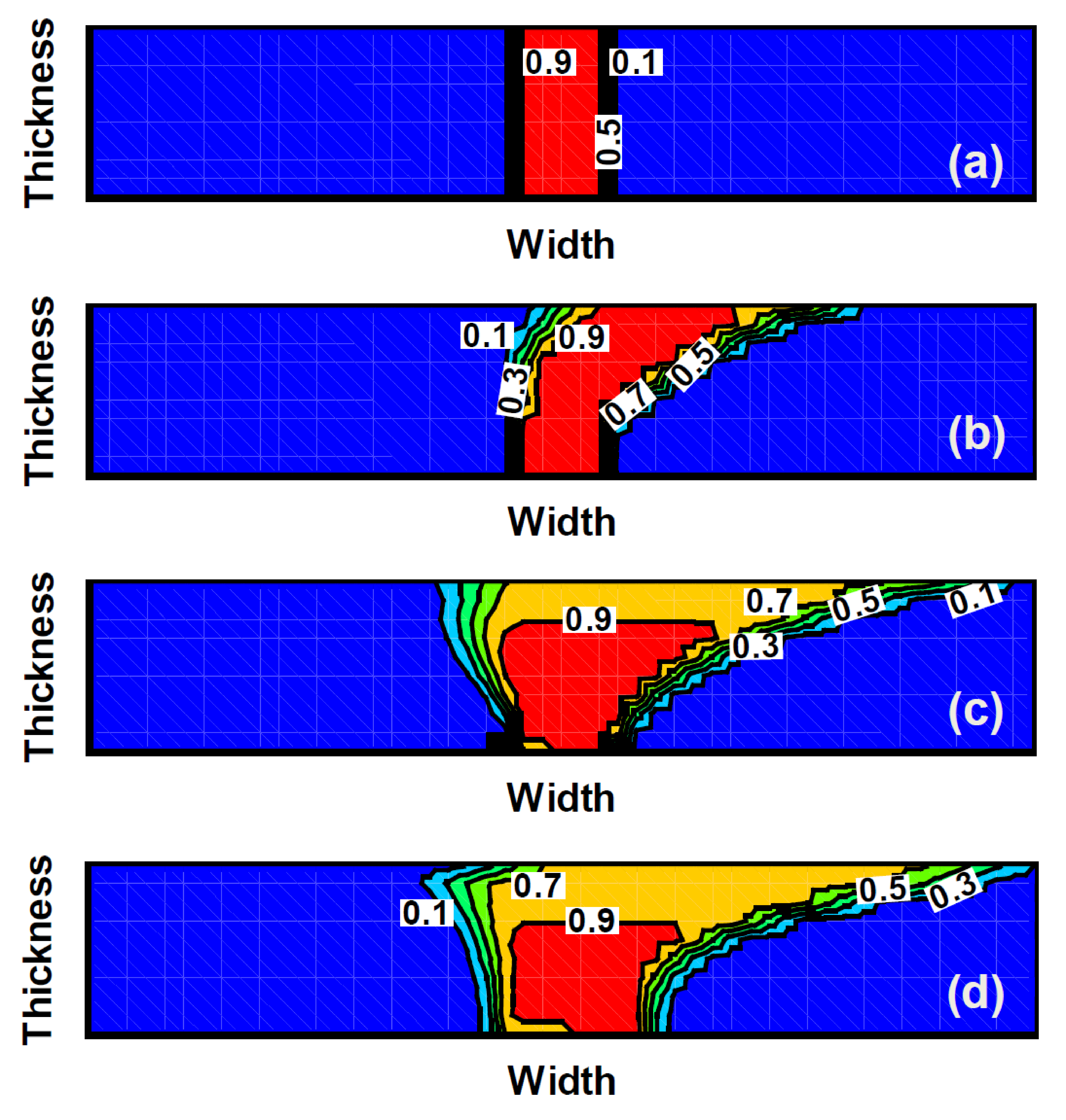
 side (a) and ending with the material-outlet
  side (d) during the steady-state
FSW process. The contour levels represent the filler-metal volume fraction for
the dissimilar filler-metal case, i.e. the filler-metal is made of AA5456-H321
and the workpiece is made of AA5083-H321. The FSW process parameters are the
same as those employed in Figures 3(a)-(d).
side (d) during the steady-state
FSW process. The contour levels represent the filler-metal volume fraction for
the dissimilar filler-metal case, i.e. the filler-metal is made of AA5456-H321
and the workpiece is made of AA5083-H321. The FSW process parameters are the
same as those employed in Figures 3(a)-(d).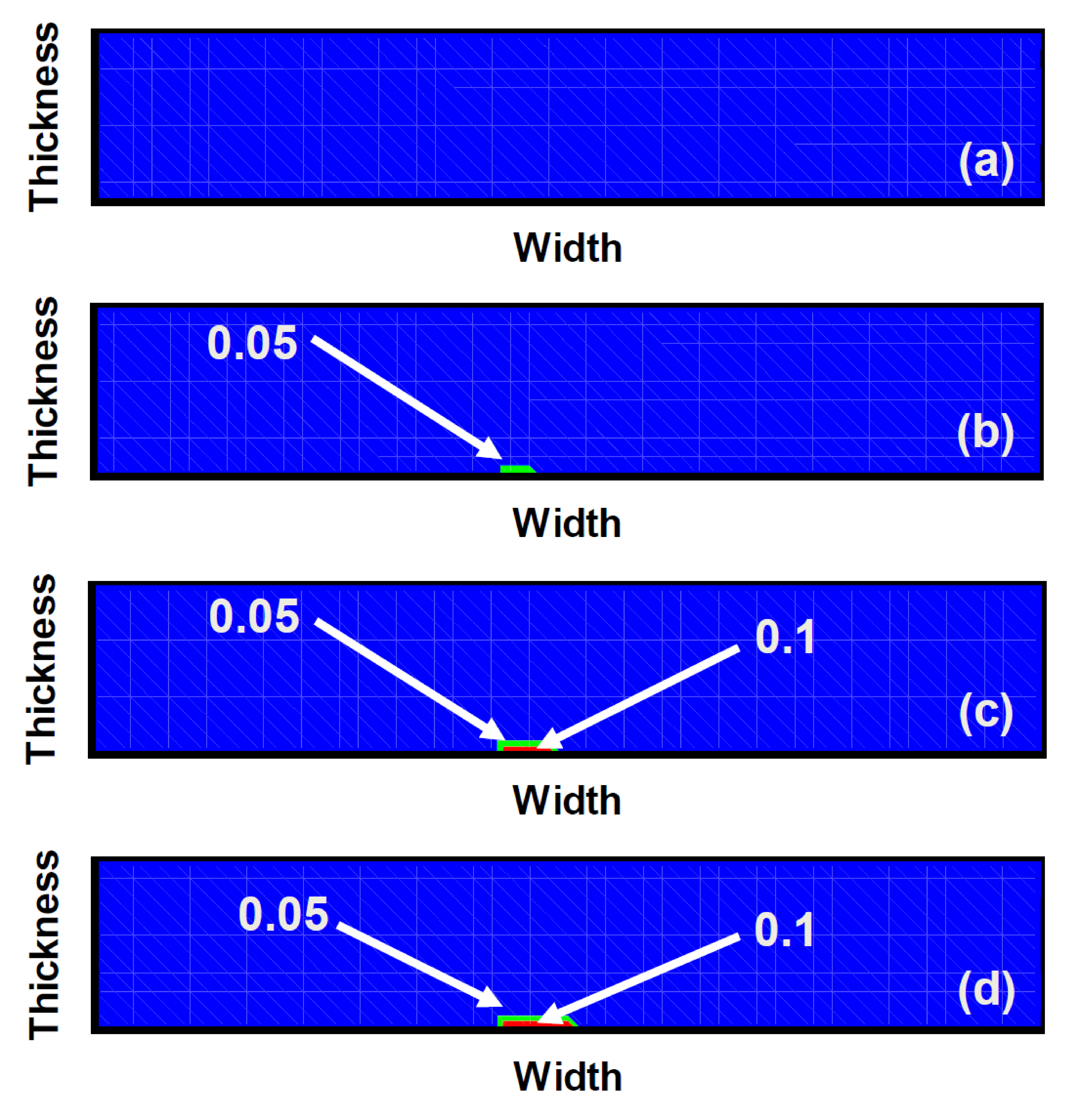 side (a) and ending with the material-outlet side (d) during the
steady-state FSW process. The contour levels represent the volume fraction of
the void-material for the dissimilar filler-metal case, i.e. the filler-metal
is made of AA5456-H321 and the workpiece is made of AA5083-H321. The FSW process
parameters are the same as those employed in Figures
3(a)-(d).
side (a) and ending with the material-outlet side (d) during the
steady-state FSW process. The contour levels represent the volume fraction of
the void-material for the dissimilar filler-metal case, i.e. the filler-metal
is made of AA5456-H321 and the workpiece is made of AA5083-H321. The FSW process
parameters are the same as those employed in Figures
3(a)-(d).3.2.2. Case B
In this subsection, an attempt was made to
remove the porosity-type flaw from the FSW joints. This was accomplished by
varying the FSW process parameters using a trial-and-error procedure. The final
set of FSW process parameters used is as follows: (a) tool rotation speed = 560
rpm; (b) tool traverse speed = 0.0022 m/sec; (c) tool tilt angle = 2.0° and (d)
tool plunge depth = 0.0001 m. In addition, the tool is positioned relative to
the weld centerline in such a way that about seven-tenths of the filler-metal
insert thickness is on the advancing side and three-tenths on the retreating
side of the weld. Figures 6(a)-(d) show contour plots of the volume fraction of
the filler-metal over different ![]() sections between the
material-inlet
sections between the
material-inlet ![]() side and material-outlet
side and material-outlet ![]() side. The corresponding plot for the
volume fraction of the void material was generated but is not shown since the
volume fraction of the voids was zero everywhere (indicating the formation of a
sound, flaw-free FSW joint). Examination of the results displayed in Figures
6(a)-(d) reveals: (a) within the weld region, mixing of the filler-metal and
base-metal materials is nearly complete; (b) the extent of filler-metal
displacement by the rotating FSW tool has been greatly reduced; and (c) the
weld is flaw-free.
side. The corresponding plot for the
volume fraction of the void material was generated but is not shown since the
volume fraction of the voids was zero everywhere (indicating the formation of a
sound, flaw-free FSW joint). Examination of the results displayed in Figures
6(a)-(d) reveals: (a) within the weld region, mixing of the filler-metal and
base-metal materials is nearly complete; (b) the extent of filler-metal
displacement by the rotating FSW tool has been greatly reduced; and (c) the
weld is flaw-free.
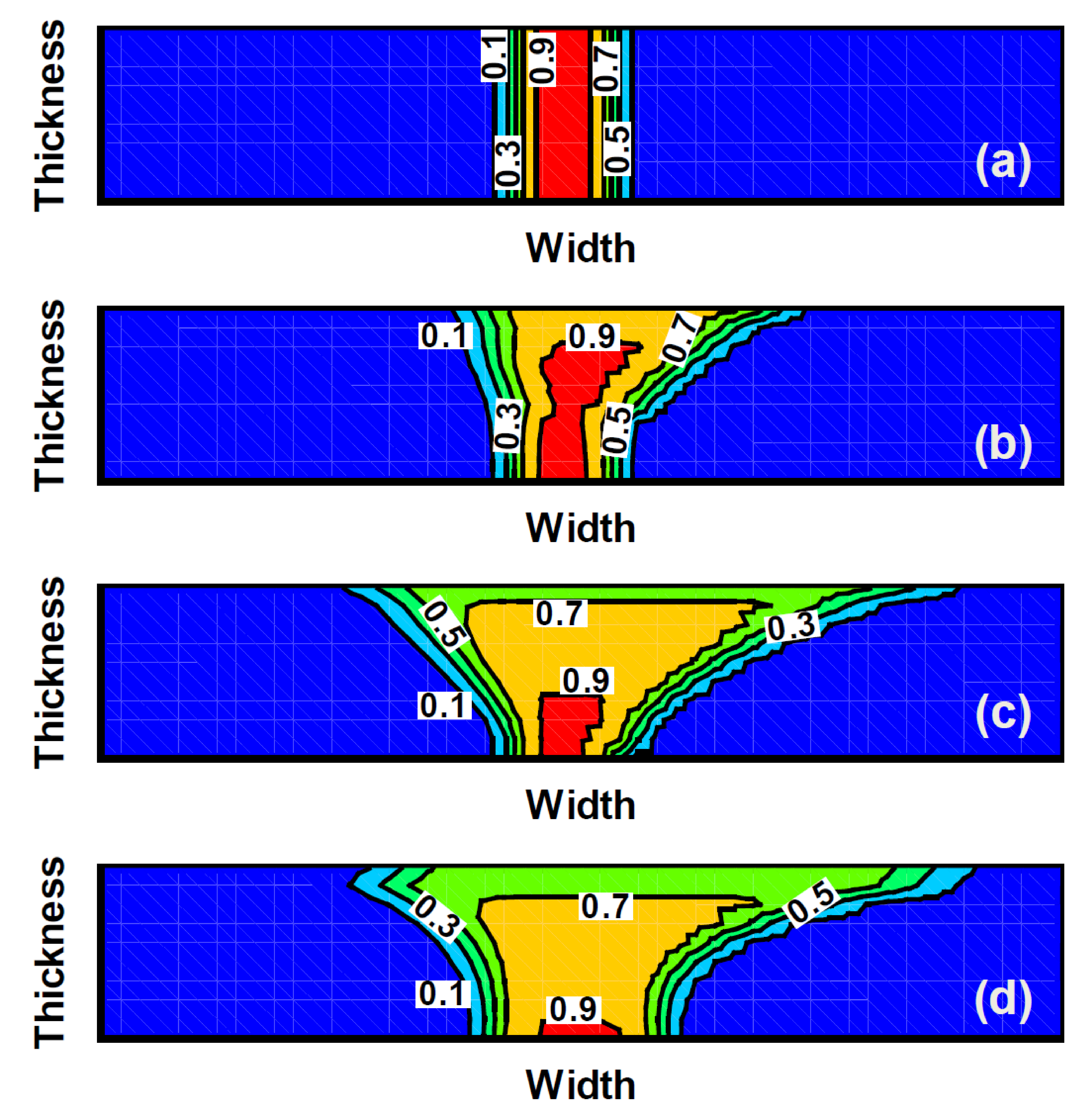
 side (a) and ending with the
material-outlet
side (a) and ending with the
material-outlet  side (d) during the steady-state
FSW process. The contour levels represent the filler-metal volume fraction for
the dissimilar filler-metal case, i.e. the filler-metal is made of AA5456-H321
and the workpiece is made of AA5083-H321. Please see text for details of the
FSW process parameters.
side (d) during the steady-state
FSW process. The contour levels represent the filler-metal volume fraction for
the dissimilar filler-metal case, i.e. the filler-metal is made of AA5456-H321
and the workpiece is made of AA5083-H321. Please see text for details of the
FSW process parameters.In order to remove weld flaws, it was observed that during the trial-and-error procedure, the tilt angle has to be set to an optimum value. The existence of an optimum tilt-angle is generally described as a trade-off between the maximization of the forging pressure (favors a large tilt-angle) and minimization of the workpiece-weld "ploughing" (favors a smaller tilt-angle).
4. Summary and Conclusions
Based on the results presented and discussed in the present work, the following main summary remarks and conclusions can be made:
- A coupled thermo-mechanical Eulerian/Lagrangian finite element analysis is carried out in order to investigate material mixing and weld-flaw formation during the dissimilar-filler-metal friction stir welding (FSW) process. Particular attention is paid to the effect of the following FSW process parameters: (a) tool rotation speed; (b) tool traverse speed; (c) tool tilt angle; and (d) tool plunge depth, and the tool position relative to the centerline of the weld.
- To ensure reliability and durability of FSW joints, criteria for the selection of the filler-metal materials for a given base-metal material have been discussed.
- The results obtained show that, while the FSW process in the case of the same-material joining is quite robust and good-quality sound welds can be obtained under a relatively large process window, such a process window is substantially smaller and displaced in the case of dissimilar-filler-metal FSW.
- 4. \\Nevertheless, the results show that if the FSW process parameters are chosen judiciously, sound welds can be obtained in the case of dissimilar-filler-metal FSW process.
Acknowledgements
The material presented in this paper is based on work supported by an Army Research Office (ARO) sponsored grant entitled "Friction Stir Welding Behavior of Selected 2000-series and 5000-series Aluminum Alloys" (Contract Number W911NF-11-1-0207). The authors are indebted to Dr. Asher Rubinstein of ARO for his continuing support and interest in the present work.
References
[1] W. M. Thomas, E. D. Nicholas, J. C. Needham, M. G. Murch, P. Temple-Smith and C. J. Dawes, "Friction Stir Butt Welding," International Patent Application No. PCT/GB92/02203, 1991. View Article
[2] C. J. Dawes and W. M. Thomas, "Friction Stir Joining of Aluminum Alloys," TWI Bulletin, vol. 6, no. 124, 1996.
[3] H. Liu, H. Fujii, M. Maeda and K. Nogi, "Tensile Properties and Fracture locations of Friction-Stir Welded joints of 6061-T6 Aluminium Alloy," Journal of Materials Science Letters, vol. 22, no. 15, pp. 1061-1063, 2003. View Article
[4] W. B. Lee, C. Y. Lee, W. S. Chang, Y. M. Yeon and S. B. Jung, "Microstructural Investigation of Friction Stir Welded Pure Titanium," Materials Letters, vol. 59, no. 26, pp. 3315-3318, 2005. View Article
[5] W. M. Thomas and E. D. Nicholas, "Friction Stir Welding for the Transportation Industries," Materials and Design, vol. 18, pp. 269-273, 1997. View Article
[6] J. Q. Su, T. W. Nelson, R. Mishra and M. Mahoney, "Microstructural Investigation of Friction Stir Welded 7050-T651 Aluminum," Acta Mater, vol. 51, no. 3, pp. 713-729, 2003. View Article
[7] O. Frigaard, Ø. Grong and O. T. Midling, "A Process Model for Friction Stir Welding of Age Hardening Aluminum Alloys," Metallurgical and Materials Transactions A, vol. 32, no. 5, pp. 1189-1200, 2001. View Article
[8] M. W. Mahoney, C. G. Rhodes, J. G. Flintoff, R. A. Spurling and W. H. Bingel, "Properties of Friction-Stir-Welded 7075 T651 Aluminum," Metallurgical and Materials Transactions A, vol. 29, no. 7, pp. 1955-1964, 1998. View Article
[9] C. G. Rhodes, M. W. Mahoney, W. H. Bingel, R. A. Spurling and C. C. Bampton, "Effect of Friction Stir Welding on Microstructure of 7075 Aluminum," Scripta Materialia, vol. 36, no. 1, pp. 69-75, 1997. View Article
[10] G. Liu, L. E. Murr, C. S. Niou, J. C. McClure and F. R. Vega, "Microstructural Aspects of the Friction-Stir-Welding of 6061-T6 Aluminum," Scripta Materialia, vol. 37, no. 3, pp. 355-361, 1997. View Article
[11] M. Grujicic, G. Arakere, C-F. Yen, and B. A. Cheeseman, "Computational Investigation of Hardness Evolution during Friction-Stir Welding of AA5083 and AA2139 Aluminum Alloys," Journal of Materials Engineering and Performance, vol. 20, no. 7, pp. 1097-1108, 2011. View Article
[12] M. Grujicic, J. S. Snipes, R. Galgalikar, S. Ramaswami, R. Yavari, C-F.Yen, and B. A. Cheeseman, "Ballistic-Failure Mechanisms in Gas Metal Arc Welds of MIL A46100 Armor-Grade Steel: A Computational Investigation," Journal of Materials Engineering and Performance, vol. 23, no. 9, pp. 3108-3125, 2014. View Article
[13] M. Grujicic, J. S. Snipes, R. Galgalikar, S. Ramaswami, R. Yavari, C.-F. Yen, B. A. Cheeseman and J. S. Montgomery, "Improved Gas Metal Arc Welding Multi-Physics Process Model and Its Application to MIL A46100 Armor-Grade Steel Butt-Welds," Multidiscipline Modeling in Materials and Structures, vol. 10, no. 2, pp. 176-210, 2014. View Article
[14] M. Grujicic, R. Yavari, S. Ramaswami, J. S. Snipes, and R. Galgalikar, "Computational Analysis of Inter-Material Mixing and Weld-Flaw Formation during Dissimilar-Filler-Metal Friction Stir Welding (FSW)," Multidiscipline Modeling in Materials and Structures, vol. 11, no. 3, pp. 322-349, 2015. View Article
[15] I. Dinaharan, K. Kalaiselvan, S.J. Vijay, P. Raja, "Effect of material location and tool rotational speed on microstructure and tensile strength of dissimilar friction stir welded aluminum alloys," Archives of Civil and Mechanical Engineering, vol. 12, no. 4, pp. 446-454, 2012. View Article
[16] M. Dehghani, A. Amadeh, and S.A.A. Akbari Mousavi, "Investigations on the effects of friction stir welding parameters on intermetallic and defect formation in joining aluminum alloy to mild steel," Materials and Design, vol. 49, pp. 433-441, 2013. View Article
[17] M. Ghosh, Md.M. Husain, K. Kumar, and S.V. Kailas, "Friction Stir-Welded Dissimilar Aluminum Alloys: Microstructure, Mechanical Properties, and Physical State," Journal of Materials Engineering and Performance, vol. 22, no. 12, pp. 3890-3901, 2013. View Article
[18] J.F. Guo, H.C. Chen, C.N. Sun, G. Bi, Z. Sun, and J. Wei, "Friction stir welding of dissimilar materials between AA6061 and AA7075 Al alloys effects of process parameters," Materials and Design, vol. 56, pp. 185-192, 2014. View Article
[19] X. Liu, S. Lan, and J. Ni, "Analysis of process parameters effects on friction stir welding of dissimilar aluminum alloy to advanced high strength steel," Materials and Design, vol. 59, pp. 50-62, 2014. View Article
[20] H. W. Zhang, and Z. Zhang, "Numerical modeling of friction stir welding process by using rate-dependent constitutive model," Journal of Materials Science and Technology, vol. 23, no. 1, pp. 73-80, 2007. View Article
[21] H. W. Zhang, Z. Zhang, J. Bie, L. Zhou, and J. T. Chen, "Effect of viscosity on material behavior in friction stir welding process," Transactions of Nonferrous Metals Society of China, vol. 16, no. 5, pp. 1045-1052, 2006. View Article
[22] M. Grujicic, G. Arakere, B. Pandurangan, A. Hariharan, C-F.Yen, B. A. Cheeseman and C. Fountzoulas, "Computational Analysis and Experimental Validation of the Friction Stir Welding Behavior of Ti-6Al-4V," Journal of Engineering Manufacture, vol. 225, no. 2, pp. 208-223, 2011. View Article
[23] M. Grujicic, T. He, G. Arakere, H. V. Yalavarthy, C-F.Yen and B. A. Cheeseman, "Fully-coupled Thermo-mechanical Finite-element Investigation of Material Evolution During Friction-Stir Welding of AA5083," Journal of Engineering Manufacture, vol. 224, no. 4, pp. 609-625, 2010. View Article
[24] M. Grujicic, G. Arakere, H. V. Yalavarthy, T. He, C-F.Yen and B. A. Cheeseman, "Modeling of AA5083 Material-Microstructure Evolution During Butt Friction-stir Welding," Journal of Materials Engineering and Performance, vol. 19, no. 5, pp. 672-684, 2010. View Article
[25] M. Grujicic, G. Arakere, B. Pandurangan, A. Hariharan, C-F.Yen, and B. A. Cheeseman, "Development of a Robust and Cost-effective Friction Stir Welding Process for use in Advanced Military Vehicle Structures," Journal of Materials Engineering and Performance, vol. 20, no. 1, pp. 11-23, 2011. View Article
[26] M. Grujicic, G. Arakere, B. Pandurangan, A. Hariharan, C-F.Yen, B. A. Cheeseman and C. Fountzoulas, "Statistical Analysis of High-Cycle Fatigue Behavior of Friction Stir Welded AA5083-H321", Journal of Materials Engineering and Performance, vol. 20, no. 6, pp. 855-864, 2011. View Article
[27] M. Grujicic, G. Arakere, A. Hariharan and B. Pandurangan, "A Concurrent Product-development Approach for Friction-stir Welded Vehicle-underbody Structures," Journal of Materials Engineering and Performance, vol. 21, no. 4, pp. 437-449, 2012. View Article
[28] M. Grujicic, G. Arakere, A. Hariharan, B. Pandurangan, "Two-level Weld-Material Homogenization Approach for Efficient Computational Analysis of Welded Structure Blast Survivability," Journal of Materials Engineering and Performance, vol. 21, no. 6, pp. 786-796, 2012. View Article
[29] M. Grujicic, G. Arakere, B. Pandurangan, J. M. Ochterbeck, C-.F. Yen, B. A. Cheeseman, A. P. Reynolds and M. A. Sutton, "Computational Analysis of Material Flow During Friction Stir Welding of AA5059 Aluminum Alloys," Journal of Materials Engineering and Performance, vol. 21, no. 9, pp. 1824-1840, 2012. View Article
[30] M. Grujicic, B. Pandurangan, C.-F. Yen and B.A. Cheeseman, "Modifications in the AA5083 Johnson-Cook Material Model for Use in Friction Stir Welding Computational Analyses," Journal of Materials Engineering and Performance, vol. 21, no. 11, pp. 2207-2217, 2012. View Article
[31] M. Grujicic, B. Pandurangan, A. Arakere, C-F. Yen and B. A. Cheeseman, "Friction Stir Weld Failure Mechanisms in Aluminum-Armor Structures under Ballistic Impact Loading Conditions," Journal of Materials Engineering and Performance, vol. 22, no. 1, pp. 30-40, 2013. View Article
[32] K. A. Fraser, L. St-Georges, L. I. Kiss, "Optimization of Friction Stir Welding Tool Advance Speed via Monte-Carlo Simulation of the Friction Stir Welding Process," Materials, vol. 7, no. 5, pp. 3435-3452, 2014. View Article
[33] A. C. F. Silva, D. F. O. Braga, M. A. V. de Figueiredo, P. M. G. P. Moreira, "Friction stir welded T-joints optimization," Materials and Design, vol. 55, pp. 120-127, 2014. View Article
[34] H. Wang, P. A. Colegrove, J. F. dos Santos, "Numerical investigation of the tool contact condition during friction stir welding of aerospace aluminium alloy," Computational Materials Science, vol. 71, pp. 101-108, 2013. View Article
[35] ABAQUS Version 6.14, User Documentation, Dassault Systems, 2014. View Article
[36] M. Grujicic, R. Yavari, J. S. Snipes, S. Ramaswami, C.-F. Yen and B. A. Cheeseman, "Linear Friction Welding Process Model for Carpenter Custom 465 Martensitic Precipitation-Hardened Stainless Steel," Journal of Materials Engineering and Performance, vol. 23, no. 6, pp. 2182-2198, 2014. View Article
[37] M. Grujicic, S. Ramaswami, J. S. Snipes, V. Avuthu, R. Galgalikar, C.-F. Yen, B. A. Cheeseman, Z. Zhang, "Prediction of the Grain-Microstructure Evolution within the Friction Stir Welding (FSW) Joint via the use of the Monte Carlo Simulation Method," Journal of Materials Engineering and Performance, vol. 24, no. 9, pp. 3471-3486, 2015. View Article
[38] Z. Zhang, Q. Wu, M. Grujicic, Z.Y. Wan, "Monte Carlo Simulation of Grain Growth and Welding Zones in Friction Stir Welding," Journal of Materials Science, vol. 51, no. 4, pp. 1882-1895, 2016. View Article
[39] G. R. Johnson and W. H. Cook, "A Constitutive Model and Data for Metals Subjected to Large Strains, High Strain Rates and High Temperatures," in Proceedings of the 7th International Symposium on Ballistics, the Hague, the Netherlands, 1983. View Article