International Journal of Mining, Materials, and Metallurgical Engineering (IJMMME)
ISSN: 2562-4571

Volume 5 - Year 2019 - Pages 1-6
DOI: 10.11159/ijmmme.2019.001
Investigation of High Energy Single Pulse Effect on Micro Arc Oxidation (MAO) Process on Aluminium
Mustafa Safa Yilmaz1, Orhan Sahin2
1Fatih Sultan Mehmet Vakif University, Aluminium Test and Training Centre, Halic Campus, İstanbul, Turkey
msyilmaz@fsm.edu.tr
2Gebze Technical University, Material Science and Engineering Department, Kocaeli, Turkey
osahin@gtu.edu.tr
Abstract - Micro Arc Oxidation (MAO) was applied by using high-energy anodic/cathodic pulses with various pulse durations. Anodic and cathodic pulse couples were kept at a constant voltage of 500 volts. Energy of each pulse increased with increasing duration of pulses. Since the aim of the present study was to investigate effect of pulse durations on MAO processing, other processing parameters such as duty cycle (8%), electrolyte temperature (25±5 °C), electrolyte composition (KOH, Na2SiO3.5H2O), process time (20 minutes), anodic pulse voltage, cathodic pulse voltage and chemical composition of substrate were all kept constant. Five different anodic and cathodic pulse durations were applied. Scanning electron microscope (SEM), indenter, profilometer, eddy current and X-ray diffractometer were employed to investigate the microstructure, hardness, surface roughness, coating thickness and phase distribution of the coatings. Varying of pulse duration occurred significant differences among coating specifications. Coating layers with thickness between 50-90 μm and surface roughness between 3.1-5.2 μm were obtained. The hardness of coating layers was between 800-2000 Vickers. Coatings consist of two sub-layers, inner dense layer and outer porous layer, which were a mixture of γ-Al2O3 and α- Al2O3.
Keywords: Aluminium, Coating, Micro Arc Oxidation, Surface characterization.
© Copyright 2018 Authors This is an Open Access article published under the Creative Commons Attribution License terms. Unrestricted use, distribution, and reproduction in any medium are permitted, provided the original work is properly cited.
Date Received: 2018-09-11
Date Accepted: 2018-11-20
Date Published: 2019-02-15
1. Introduction
Aluminium and its alloys used in various industries such as automotive, aerospace and transportation. Interest in aluminium and its alloys comes from their high strength to weight ratio and convenient corrosion resistance. On the other hand, their disadvantages are low wear resistance, low hardness and hard to lubricate, hence they have limited usage area [1]. Some surface treatment methods have applied on aluminium alloys for improving their mechanical and tribological properties [2-5]. One of these surface treatment methods is MAO that forms thick and hard alumina coating having high wear resistance, thermal resistance and corrosion resistance [6-9]. The properties of MAO coating are identified by some parameters, such as electrolyte composition, applied power modes, additives, processing temperature, chemical composition of substrate, processing time, etc. [6]. Currently it has been investigated that bipolar pulsed current mode formed thicker and more uniform coatings than DC and AC unipolar pulse current mode [8].
Literature showed that the electrical parameters, such as current mode, applied voltage and applied current, etc., made differences on MAO coatings. However, our knowledge on the effect of pulse duration on coating properties was not yet investigated. Thus, the aim of this study was to examine the effect of anodic-cathodic pulse couple duration’s on microstructure and morphology of MAO coatings on aluminium alloy.
2. Experimental Details
MAO processing unite has with two high frequency converters (HFC), which operate separately. One of them has positive polarity and other has negative polarity. Power of each is 12,5 kW. Voltage range of HFC’s are in between 0–800 V. The schematic picture of the MAO device is given in Figure 1 [10]. Bipolar pulse current mode was used in present research. The Tektronix-TDS 2024C digital storage oscilloscope was used to control of voltages, pulse durations and amplitudes. The electrolyte temperature was maintained via cooling system, which has refrigerant water in the spiral copper tube.

Mitutoyo SJ-400 profilometer was used for the surface roughness measurement. In addition, Fisher-Dualscope MP40E-S was performed for the coating thickness measurement. Brukers D8 (40 kW, 40 mA) type X-ray diffract meter was used for identification of the phases. X-ray diffraction (XRD) was conducted with Cu Kα radiation. Between 20° to 90° degrees were scanned with a step increment of 0.02° and an account time of 1 s. Cross-sectional microstructural analyses were investigated by Philips XL30 type field emission Scanning Electron Microscopy (SEM). Mitutoyo MicroWizhard micro-hardness tester was used for cross-sectional hardness tests under indentation load of 20 gr. The elemental analysis of the aluminium substrates was investigated with Spectro-Max LMF14 spectroscopy measurement device and the results are given in Table 1.
Table 1. Spectral analysis of substrate.
| Al | Si | Mg | Cu | Mn | Fe | Zn | Sn | Pb |
| 98,6 | 0,47 | 0,46 | 0,03 | 0,017 | 0,25 | 0,011 | 0,06 | 0,042 |
The processing surface area of samples was 4 cm2. All substrates were mechanically grounded with 200-1200 mesh emery papers and cleaned ultrasonically for 5 min with acetone.
There are several electrical process parameters that could be investigated but in this study the pulse durations effects searched, thus some other parameters were kept constant and they were given in Table 2.
Table 2. Constant parameters and their values.
| Parameter | Values |
| Anode voltage(Va) | 500 V |
| Cathode voltage(Vk) | 500 V |
| Duty cycle | 8% |
| Coating time | 20 minutes |
| Electrolyte temperature | 25±5 °C |
| Electrolyte composition | KOH (2 g/l), Na2SiO3.5H2O (9,5 g/l) |
Pulse duration couples and the sample codes were given in Table 3.
Table 3. Pulse duration's couple's values.
| Cathode pulse duration, µs | 200 | 600 | 800 | 1000 | 2500 |
| Anode pulse duration, µs | 300 | 800 | 1000 | 1800 | 3800 |
| Pulse duration couple code | C1 | C2 | C3 | C4 | C5 |
3. Results and Discussion
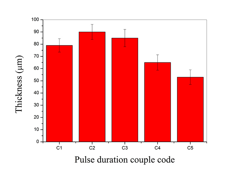
Thickness of coatings was given in Figure 2. Three different regimes of coating were formed with increasing durations of pulse couples. For short pulse duration thickness is around 80 μm (C1), increasing pulse duration caused a thicker coating layer, between 85 and 90 μm (C2, C3), longest pulse durations lowered the coating thickness (C4, C5).
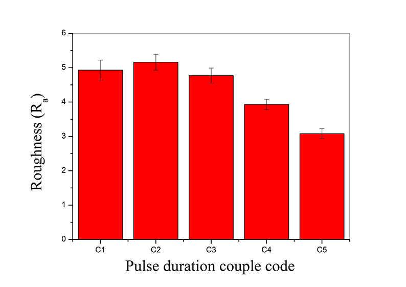
The surface roughness of MAO coatings results under different pulse duration couple modes is shown in Figure 3. Roughness was calculated of 9 measurements from different locations. It was obvious that the surface roughness’ results are in the same direction with coating thickness. It should also be noted that [6, 9-11] surface roughness was closely related with the coating thickness.
The effect of pulse duration on phase composition of MAO coatings was examined by XRD and given in Figure 4. The diffraction peaks of Al and Mg2Si were obtained from the Al alloy substrate, which stated that the content of Al is most. The reason for this is that; the structure of the coatings, which has a lot of pores and micro cracks through to the substrate and X-rays can detect the substrate material. Thus, the increasing of coating thickness decreased the strength of the substrate peaks. The characteristic peaks corresponding to γ-Al2O3 and α-Al2O3. Therefore, it can be concluded that the aluminium oxides in the MAO coatings was mainly crystalline.
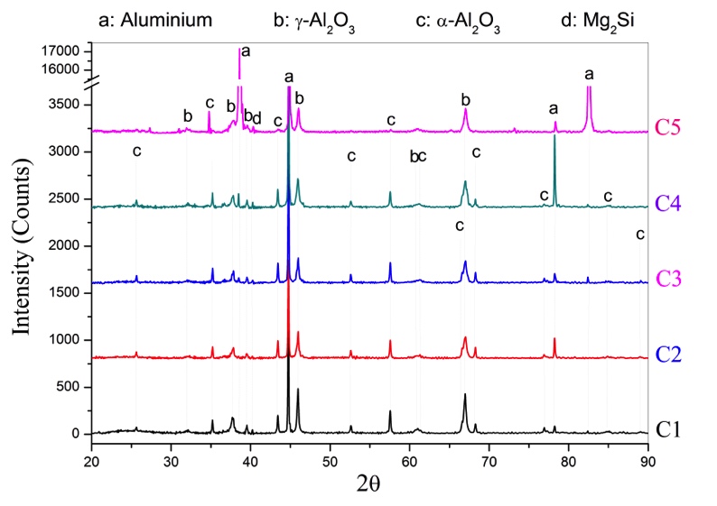
It was clearly understood from Figure 4 is that all MAO coated specimens have the γ-Al2O3 peaks and with increasing of coating thickness the intensity of α-Al2O3 increased either. Thus, the results of the XRD analysis further verified that MAO coatings had a more intense structure with increasing durations of pulse couple. On the other hand, long pulse duration damages the phase orientation via cracking the outer porous layer made the coatings thinner. Due to the thin coating layer phase transformation (from γ-Al2O3 to α-Al2O3 phase) could not occurred [8].
The hardness profiles of coatings were given in Figure 5. Due to nature of the MAO process; the outer layer has a porous structure, which is mostly consisted of γ-Al2O3 phase, while the inner layer is a compact structure and it is mostly consisted of α-Al2O3 phase [10, 12]. This lamination had affected the hardness profile results by the distance from surface.
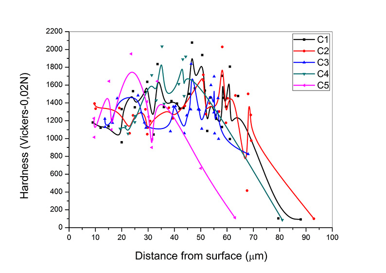
The hardness profiles began with 1100-1300 Vickers from the surface, which has porous outer layer. With the increasing of distance from surface, hardness was increased and reaches 2000 Vickers’ s at the depth of approximately 30 µm from the coating surface. This hard area is mostly consisting of α-Al2O3 phase. Because of hard α-Al2O3 phase was present very near to the substrate-coating interface [13], the points at which hardness data was measured were in between 30 and 60 µm from the coating surface. Although it is high hardness, is not high enough as expected. Due to the nature of the process there occurred micro pores and micro cracks inside of the coating that the hardness of the coating reduced [10]. The hardness decreased dramatically at the depth of 70 µm from the coating surface where the presence of substrate began.
It is clear that there is no significant difference on coating hardness with the increasing in pulse duration. Nevertheless, the average hardness of the coatings decreases with the pores and cracks [10]. Although sample C5 has low α-Al2O3 phase, its average hardness almost same with other parameters. This result may interpretable with the pore distributions of the samples.
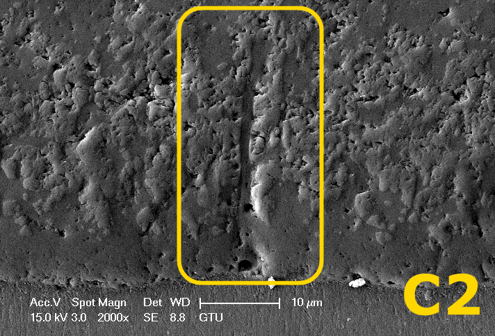
Cross sectional SEM image of sample C2 was given in Figure 6. Sparks discharge micro channels may reach to the substrate from the surface of the coating as shown in Figure 6. This micro channel carries the molten metal though to surface and solidified on it. This rapid solidification of the molten alumina caused micro cracks and pores in surface of coating [10, 14].
By increasing the thickness of coating, transformation from γ-Al2O3 phase to α-Al2O3 phase began in inner layer. It has reported that γ-Al2O3 phase formed due to the high cooling rate, while more α-Al2O3 phase could be explored in the inner layers due to the low cooling rate [9]. With cross sectional micrographs, Figure 6, we found the inner layer demonstrated as an orange peel appearance.
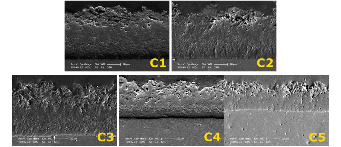
Cross sectional SEM images of C1, C2, C3, C4 and C5 were given in Figure 7. The outer layers of C2-C3 have more micro pores compared with C1, due to the long pulse durations. On the other hand, long pulse duration generated more α-Al2O3 phase and thicker coating in contrast with C1. On the other hand, increasing in porous outer layer increased the coating thickness. With the increasing thickness the phase formation began, and the α-Al2O3 phase contents increased, these results proved with XRD analysis and SEM micrographs (orange peel areas).
Increasing the anodic-cathodic pulse durations, like as C4-C5, has clearly damaged the coating layers and decreased the coating thickness due to the strong discharge phenomena. The thicknesses are reduced and there is almost no orange peel appearance (Means that the content of α-Al2O3 phase decreased) on cross-sectional morphology of C5, Figure 7.
With the qualitative analyse; coatings porosity depends on the pulse durations. Increased in duration the coating porosity increased and the coating thickness increased either. Further increase in duration the coatings damaged and decreased in thickness. This decrease in thickness affect the composition of the coating such as decreased in α-Al2O3 phase areas (orange peel areas). On the other hand, the porosity significantly affects the hardness, for instance in a ceramic body hardness decreases 60-70% due to the 20% porosity [15].
5. Conclusion
In this paper the effect of durations of pulse couple on properties of coating was investigated at five different pulse duration parameters.
It was found that short pulse durations formed high quality inner dense layer. Increasing of pulse duration’s lead to a significant increase in both coating thickness and volume percent of pores. It is obvious that these pores are effective of the increasing of coating thickness.
Hardness and XRD phase analysis proved that α- Al2O3 was obtained for whole range of pulse durations. Increase in hardness apparently is due to the combine effect of increase in volume percent of α-Al2O3 and decrease in volume percent of pores.
A coating layer of 90 µm was achieved by 20 minutes of processing time that is rate of growth is 4.5 µm/min with experiment C3. Succeeding of this growth rate is an evidence of that the present process is energy efficient and no need higher pulse duration than that of experiment C1.
For further increase in quality of coating, investigations on other electrical parameters of processing are needed. Also corrosion, wear and bioactivity of the coatings are future investigations.
6. Acknowledgements
The authors express their thanks to technicians Adem Sen and Ahmet Nazim for their kind assistance during XRD and SEM experimental studies. The authors would like to acknowledge Metehan Unlu for helping with editing of the paper. The work was carried out with financial support from the Scientific and Technological Research Council of Turkey (TUBITAK) / Project Name: 2211-C Scholarship of National Priority Subjects Doctoral Thesis Programme.
References
[1] Z. J. Wang, L. N. Wu, Y. L. Qi, W. Cai, Z. H. Jiang, “Self-lubricating Al2O3/PTFE composite coating formation on surface of aluminium alloy,” Surface and Coatings Technology, vol. 204, no. 20, pp. 3315-3318, 2010. View Article
[2] C. Taschner, B. Ljungberg, V. Alfredsson, I. Endler, A. Leonhardt, “Deposition of hard crystalline Al2O3 coatings by bipolar pulsed dc PACVD,” Surface and Coatings Technology, vol. 108, pp. 257-264, 1998. View Article
[3] F. Fietzke, K. Goedicke, W. Hempel, “The deposition of hard crystalline Al2O3 layers by means of bipolar pulsed magnetron sputtering,” Surface and Coatings Technology, vol. 86-7, no. 2, pp. 657-663, 1996. View Article
[4] R. Emmerich, B. Enders, H. Martin, F. Stippich, G. K. Wolf, P. E. Andersen, J. Kudelha, P. Lukac, H. Hasuyama, Y. Shima, “Corrosion protection ability of Al2O3 coatings deposited with ion beam assisted deposition,” Surface and Coatings Technology, vol. 89, no. 1-2, pp. 47-51, 1997. View Article
[5] B. H. Kear, Z. Kalman, R. K. Sadangi, G. Skandan, J. Colaizzi, W. E. Mayo, “Plasma-sprayed nanostructured Al2O3/TiO2 powders and coatings,” Journal of Thermal Spray Technology, vol. 9, no. 4, pp. 483-487, 2000. View Article
[6] A. L. Yerokhin, X. Nie, A. Leyland, A. Matthews, S. J. Dowey, “Plasma electrolysis for surface engineering,” Surface and Coatings Technology, vol. 122, no 2-3, pp. 73-93, 1999. View Article
[7] L. O. Snizhko, A. L. Yerokhin, N. L. Gurevina, V. A. Patalakha, A. Matthews, “Excessive oxygen evolution during plasma electrolytic oxidation of aluminium,” Thin Solid Films, vol. 516, no.2-4, pp. 460-464, 2007. View Article
[8] A. L. Yerokhin, A. Shatrov, V. Samsonov, P. Shashkov, A. Pilkington, A. Leyland, A. Matthews, “Oxide ceramic coatings on aluminium alloys produced by a pulsed bipolar plasma electrolytic oxidation process,” Surface and Coatings Technology, vol. 199, no. 2-3, pp. 150-157, 2005. View Article
[9] T. B. Wei, F. Y. Yan, J. Tian, “Characterization and wear- and corrosion-resistance of microarc oxidation ceramic coatings on aluminium alloy,” Journal of Alloys and Compounds, vol. 389, no.1, pp. 169-176, 2005. View Article
[10] M. S. Yilmaz, O. Sahin, “Applying High Voltage Cathodic Pulse with Various Pulse Durations on Aluminium via Micro-Arc Oxidation (MAO),” Surface and Coatings Technology, vol. 347, pp. 278-285, 2018. View Article
[11] M. S. Yilmaz, O. Sahin, “Effects of Pulse Duration on Structure and Surface Characteristics of Micro-Arc Oxidation Coatings Formed on Aluminium Alloy,” Acta Physica Polonica A, vol. 129, no. 4, pp. 673-676, 2016. View Article
[12] Y. J. Guan, Y. Xia, G. Li, “Growth mechanism and corrosion behaviour of ceramic coatings on aluminium produced by autocontrol AC pulse PEO,” Surface and Coatings Technology, vol. 202, no. 19, pp. 4602-4612, 2008. View Article
[13] W. B. Xue, X. L. Wu, X. J. Li, H. Tian, “Anti-corrosion film on 2024/SiC aluminium matrix composite fabricated by microarc oxidation in silicate electrolyte,” Journal of Alloys and Compounds, vol. 425, no.1-2, pp. 302-306, 2006. View Article
[14] K. Wang, B. H. Koo, C. G. Lee, Y. J. Kim, S. H. Lee, E. Byon, “Effects of electrolytes variation on formation of oxide layers of 6061 Al alloys by plasma electrolytic oxidation,” Transactions of Nonferrous Metals Society of China, vol. 19, no. 4, pp. 866-870, 2009. View Article
[15] J. A. Curran, T. W. Clyne, “Porosity in plasma electrolytic oxide coatings,” Acta Materialia, vol. 54, no. 7, pp. 1985-1993, 2006. View Article