International Journal of Mining, Materials, and Metallurgical Engineering (IJMMME)
ISSN: 2562-4571

Volume 11 - Year 2025 - Pages 1-7
DOI: 10.11159.ijmmme.2025.001
The Effects of Dispersant on Slurry Properties and Electrochemical Behavior of LiMn0.6Fe0.4PO4/Graphite Batteries
Chanmonirath (Michael) Chak1,2, Vadim Shipitsyn1,2, Lin Ma1,2*, Joseph E. Remias3
1University of North Carolina at Charlotte, Department of Mechanical Engineering and Engineering Science
9201 University City Blvd, Charlotte, NC, USA 28223
2University of North Carolina at Chapel Hill, Department of Applied Physical Sciences
200 E Cameron Ave, Chapel Hill, NC, USA 27599
3Afton Chemical Corporation
500 Spring Street, Richmond, VA, USA 23219
*Corresponding author: L.ma@unc.edu
Abstract - Phase separation during the slurry preparation process significantly shortens the slurry’s usable lifetime, negatively impacting coating uniformity on the current collector and degrading electrochemical performance. This study investigates the effect of a small amount of proprietary dispersant on the slurry stability and electrochemical behavior of LiMn0.6Fe0.4PO4 (LMFP) cathode. Three dispersant concentrations were tested and compared with a pristine sample containing no dispersant. A combination of digital microscopy, slurry storage evaluation, scanning electron microscopy, electrochemical impedance spectroscopy, and long-term cycling were used to assess the influence of dispersant on both slurry behavior and electrode performance. Results demonstrate that even a small amount, 0.01 wt%, of proprietary dispersant effectively suppresses phase separation, enabling better slurry handling and coating consistency, while preserving the electrode’s morphology and electrochemical performance. These findings support the use of optimized dispersant strategies in the scalable production of LMFP electrodes.
Keywords: dispersant, slurry, LiMn0.6Fe0.4PO4, electrochemical performance, lithium-ion batteries.
© Copyright 2025 Authors This is an Open Access article published under the Creative Commons Attribution License terms. Unrestricted use, distribution, and reproduction in any medium are permitted, provided the original work is properly cited.
Date Received: 2025-11-17
Date Revised: 2025-12-11
Date Accepted: 2025-12-19
Date Published: 2025-12-29
1. Introduction
The development of advanced lithium-ion battery (LIB) cathode materials requires a balance of electrochemical performance, cost, safety, manufacturability, and the raw material availability [1]. LiMnxFe1-xPO4 (LMFP) offers a promising alternative to the widely commercialized LiFePO4 (LFP), combining moderate energy density, excellent thermal stability, and low material cost, without relying on critical materials like nickel (Ni) and cobalt (Co)[2, 3]. In LMFP, partial substitution of iron (Fe) with manganese (Mn) introduces the Mn2+/Mn3+ redox couple, which operates at a higher potential than the Fe2+/Fe3+ redox couple, thereby increasing energy density [4]. With the use of abundant Mn and Fe, LMFP becomes an attractive option for enhancing battery performance without significantly increasing production costs, particularly when compared to other high Ni containing cathode materials.
The slurry-making process is the standard method for fabricating cathode electrodes in LIBs, involving the mixing of active materials, conductive additives, and binders in a solvent to form a uniform suspension. However, achieving and maintaining unform dispersion in the slurry medium remains a key challenge. Inadequate dispersion can lead to particle agglomeration, inhomogeneous electrode structure, and ultimately degrades battery performance [5]. Additionally, during the manufacturing process, not all slurries are used immediately, and prolonged storage can lead to sedimentation, further affecting slurry consistency. Adding dispersants is an effective strategy to mitigate this issue, as they help stabilize the suspension and improve overall slurry processability. Despite their critical role, only a limited number of studies have explored the correlation between dispersant properties and electrochemical properties in the slurry medium. Hagiwara et al. developed dispersants capable of lowering slurry viscosity even under low N-methyl-2-pyrrolidone (NMP) content, while minimizing adverse effects on electrochemical behavior [6]. Chang et al. demonstrated that a carbon-based electrically conductive particle (cECP) dispersant enhanced slurry homogeneity, leading to improved electrode structure and battery performance by forming a more cohesive conductive network between active material particles [7]. Similarly, Lee et al. reported that incorporating poly(acrylic acid) (PAA) not only reduced the viscosity of C/LFP slurries but also promoted finer particle dispersion, resulting in enhanced rate capability [8]. These findings highlight the potential of dispersants to significantly improve both the manufacturing process and electrochemical performance of LIBs.
The aim of this work is to investigate the effect of a proprietary dispersant sample on the dispersion behavior of LMFP and its electrochemical performance for application in LIBs. The impact of incorporating the sample dispersant into LMFP slurries was assessed by monitoring slurry phase separation over time and evaluating the electrochemical behavior of coin cells fabricated from the formulated slurries. Through this approach, the study aims to provide insight into the role of dispersants in enhancing both the processability and functional performance of LMFP electrodes, with potential implications for their use in large-scale, cost-sensitive applications such as grid energy storage.
2. Materials and Methods
2. 1. Cathode slurry preparation
A commercial surfactant sample was obtained from Afton Chemical Corporation (based in Richmond, Virginia, USA) and incorporated into cathode slurries at varying concentrations to evaluate its effect on slurry properties. The dispersant used (hereinafter referred to as “Afton dispersant”) is a quaternary ammonium salt compound obtained by reacting maleated polyisobutylene (Mn 1000) with 3-(2-(dimethylamino) ethoxy) propylamine, and then quaternaizing the amino group with dimethyl oxalate.
Four types of slurries were prepared: a pristine sample without dispersant and three samples containing 0.01 wt%, 0.05 wt%, and 0.5 wt% of dispersant, respectively. To prepare the dispersant solution, the material was dissolved in N-methyl-2-pyrrolidone (NMP, Sigma-Aldrich, 99.5%) at the designated concentrations and stored at 60 °C for 24 h to ensure complete mixing. The cathode slurries were then formulated by mixing LiMn0.6Fe0.4PO4 (LMFP, Dynanonic), polyvinylidene fluoride (PVDF Kynar 301 F, Arkema) and carbon black (Super P, Timcal) in a mass ratio of 93:4:3. Either pure NMP or the prepared dispersant-NMP solution was added to the solid mixture at a solid-to-liquid weight ratio of 1:1. Slurries were mixed using a planetary centrifugal mixer (Thinky AR-100, Tokyo, Japan) at 2000 rpm for 10 minutes, followed by a 1-minute defoaming step at the same rotation speed.
To ensure reproducibility, the slurry temperature and viscosity consistency were monitored during preparation. The mixing process resulted in a minimal temperature increase of less than 3 °C across all batches, which is not sufficient to influence PVDF dissolution or carbon dispersion. For each formulation, slurries were prepared using an identical solid-to-liquid ratio and mixing protocol, and visual flow assessment confirmed that batches within the same slurry type exhibited comparable viscosity prior to coating.
2. 2. Cathode electrode preparation
The prepared cathode slurries were uniformly coated onto clean aluminum foil current collectors using a 0.006” (~150 µm) notch bar by manual casting. The slurry coatings were first dried under ambient conditions in a fume hood for 1 h, followed by further drying in a vacuum oven at 120 °C and 2 h. The resulting electrodes were then punched into circular disks with an 11 mm diameter and subjected to an additional vacuum drying step at 100 ºC for 12 h to ensure complete removal of residual solvent. The cathode electrodes exhibited an active material mass loading of approximately 7-8 mg cm-2 and a corresponding capacity loading of 1.05-1.20 mAh cm-2 (based on theoretical capacity of 150 mAh g-1). Subsequently, the cathode electrodes were transferred into an argon-filled glovebox (O2, H2O < 0.01 ppm) for assembly of CR2032 coin cells. Detailed procedures for coin-cell electrode fabrication was adapted from the method reported by Marks et al. [9].
2. 3. Coin cell preparation
Full coin-cell assemblies were carried out in an argon-filled glovebox (O2, H2O < 0.01 ppm) using the fabricated cathode, a polyethylene (PE, Celgard) separator, and a graphite anode (MTI Corporation) with a diameter of 13 mm. The cells were constructed using a stainless-steel base, a polypropylene (PP) gasket, a 1.5 mm stainless-steel spacer, a stainless-steel disc spring, and an aluminum cap. The electrolyte consisted of 1 m lithium hexafluorophosphate (LiPF6) dissolved in a 3:7 (v/v) mixture of ethylene carbonate (EC) and ethyl methyl carbonate (EMC) (CapChem, Shenzhen, China) and was used as received. Electrolyte preparation and cell assemblies were performed entirely within the glovebox. The full coin-cell fabrication procedure was adapted from the method reported by Murray et al. [10].
2. 4. Electrochemical testing
Electrochemical testing was conducted using a Neware battery testing system (Shenzhen, China). All specific currents were calculated based on the mass of active material in the cathode electrode. Cells were cycled using a constant current (CC) protocol between 3.0 and 4.2 V vs. graphite at a rate of C/20 (7.5 mA g-1) and 25 °C.
EIS measurements were performed before and after cycling at 3.9 V (corresponding to ~50 % state of charge (SOC)) at room temperature. The data were collected using a BioLogic VMP3 electrochemical workstation, with ten data points per decade over a frequency range of 100 kHz to 100 mHz. A sinusoidal perturbation amplitude of 10 mV was applied during the measurements.
2. 5. Material Characterizations
A digital microscope (Keyence VHX-7000, Osaka, Japan) was used to monitor phase separation in the pristine slurry and the slurry containing 0.01 wt% Afton dispersant. Images of the cathode slurries were captured at 0 h, 3 days, 6 days, and 10 days to observe changes in slurry homogeneity over time.
SEM images were acquired using a JEOL JSM-6480 instrument (Tokyo, Japan). The microscope was equipped with a tungsten (W) filament as the electron source and operated in secondary electron mode at an accelerating voltage of 20 kV.
3. Results and Discussion
To investigate the influence of dispersant concentration on slurry quality, electrode performance, slurries were prepared with three different concentrations of Afton dispersant: 0.01 wt%, 0.05 wt%, and 0.5 wt%. These were compared to a pristine slurry that contained no dispersant. After mixing, all the slurries appeared visually homogenous and well-dispersed. The prepared slurries were then used to fabricate LMFP electrodes, allowing a systematic evaluation of how varying amounts of dispersant affect electrode morphology and electrochemical behavior first.
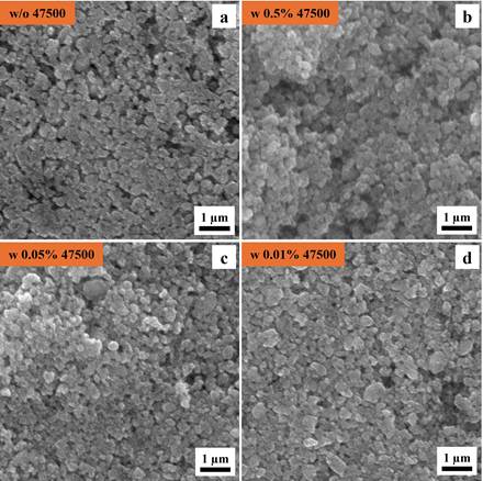
Figure. 1 shows SEM images of LMFP electrodes prepared without dispersant (Figure. 1a) and varying concentrations of Afton dispersant, including 0.5 wt% (Figure 1b), 0.05 wt% (Figure 1c) and 0.01 wt% (Figure 1d). All electrode surfaces display nanoscale particles, which are characteristic of olivine-type phosphate cathode materials. The addition of Afton dispersant does not alter the morphology of the LMFP electrodes, indicating that the dispersant is compatible with the LMFP material during the slurry preparation and does not negatively impact the microstructure.
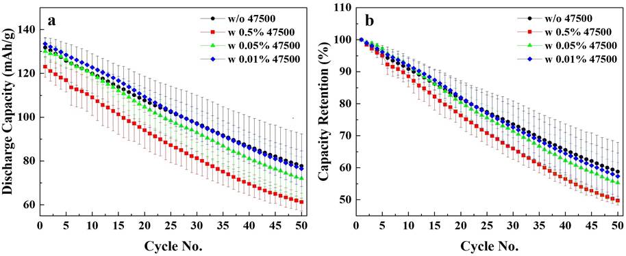
To better assess the influence of dispersant concentration on the electrochemical performance of LMFP electrodes, LMFP/graphite coin cells were assembled. Figure. 2 shows the cycling performance of LMFP electrodes with varying concentrations of Afton dispersant, evaluated at a C/20 rate over 50 cycles at room temperature. Figure. 2a shows the discharge capacity as a function of cycle number, Figure. 2b shows the corresponding normalized capacity retention. To ensure repeatability, two-coin cells were tested per condition. Average results were shown in each data point with standard deviation error bars. Among the dispersant-containing samples, the electrode with 0.01 wt% Afton dispersant (blue curves) exhibited the best discharge capacity retention during cycling throughout the 50-cycle test. The control sample without dispersant (black curve) demonstrated a similar electrochemical performance to the 0.01 wt% sample, suggesting that a minimal amount of dispersant may be sufficient to maintain the similar electrochemical performance. The electrode containing 0.05 wt% dispersant (green curve) showed slightly faster capacity fading compared to the 0.01 wt% sample, though still within the error deviation of the test. This may be showing initial signs that increased dispersant content may not necessarily lead to better electrochemical stability. Notably, the sample with the highest concentration, 0.5 wt% (red curve), showed the poorest performance among the dispersant-containing electrodes, with both lower specific capacity and faster degradation. These findings highlight the importance of carefully tuning the dispersant concentration, with 0.01 wt% or lower identified as optimal range for achieving stable, high-performance full-cell operation.
Figure. 3 shows the area-specific Nyquist plots of LMFP/graphite coin cells without and with different concentrations of Afton dispersant. The EIS measurements were conducted at 3.9 V and room temperature, both before cycling and after 50 cycles, to evaluate changes in impedance associated with cycling. After formation, the 0.01 wt% Afton dispersant containing cell exhibited the lowest initial impedance, indicating improved charge transfer kinetics. With the increase in concentration of Afton dispersant, the impedance becomes higher. In contrast, the control sample (without dispersant) displayed the highest impedance after formation. After 50 cycles, all samples showed an increase in impedance, but to varying degrees. The control sample exhibited modest impedance growth, whereas the 0.01 wt% sample experienced a greater rise. Despite this increase, the 0.01 wt% sample still maintained competitive overall impedance compared to the samples with higher dispersant content. The continued trend of increasing impedance with increasing dispersant concentration was observed by post-cycling. These results emphasize the need to optimize dispersant content to balance initial performance with long-term impedance growth.

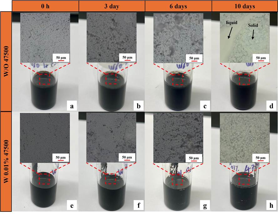
Given that 0.01 wt% dispersant does not compromise battery cycling performance and causes minimal impedance increase, slurry storage tests were conducted to further assess its effectiveness in preventing sedimentation over time. Figure. 4 illustrates the temporal evolution of LMFP slurries without Aton dispersant (Figure 4a-d) and with 0.01 wt% Afton dispersant (Figure 4e-h). Digital microscope images are embedded within each corresponding slurry image to provide a closer look at the dispersion state of the particles. At 0 hours, both slurries, with and without Afton dispersant, initially appeared homogeneous, suggesting that both formulations could be effectively mixed under the same processing conditions. However, the slurry without the Afton dispersant exhibited increasing sedimentation over time. Sedimentation is a common phenomenon in particle suspensions where, in the absence of sufficient steric or electrostatic stabilization, heavier solid particles tend to settle at the bottom due to gravity. Starting from day 6, visible phase separation began to appear in the slurry without the dispersant, as seen in both the glass vial and the corresponding microscopic image, indicating that the solid particles were no longer evenly suspended in the liquid medium. This separation became more pronounced by day 10, where a distinct boundary between the sedimented solid phase and the supernatant liquid was clearly visible, confirming a significant loss of dispersion stability. In contrast, the slurry containing 0.01 wt% Afton dispersant maintained a uniform and homogeneous appearance throughout the same period. The consistent appearance under both macroscopic and microscopic observation highlights the effectiveness of the test component as a dispersant. The surfactant used has a composition with a long polymeric tail and an ionic head group. These attributes likely lead to steric hindrance and electrostatic repulsion respectively compared to the control that prevented particle agglomeration and sedimentation, thereby preserving the homogeneity of the slurry over time.
4. Conclusion
In this work, the effect of an Afton dispersant sample was systematically investigated through LMFP cathode slurry behavior and full-cell performance using LMFP/graphite coin cells. These findings clearly demonstrate that the incorporation of the Afton dispersant significantly enhances the dispersion stability and homogeneity of LMFP slurries, likely due to its steric hindrance and electrostatic repulsion, thereby minimizing particle agglomeration and sedimentation. Among the concentrations tested, 0.01 wt% emerged as the most effective, offering a balance between stable cycling behavior, and minimal impedance growth. In contrast, excessive dispersant levels were found to negatively impact cell performance with faster capacity decay and higher impedance growth. These results highlight the critical importance of dispersant optimization, with low concentrations (around 0.01 wt%) offering an effective balance between slurry processability and long-term electrochemical efficiency.
Beyond laboratory-scale testing, improved dispersion at 0.01 wt% may also aid large-scale electrode fabrication by helping maintain consistent slurry flow during roll-to-roll coating. While the stabilization mechanism identified here is expected to remain relevant at higher solid-to-liquid ratios (>60 wt%) commonly used in industry, the optimal concentration may differ under those conditions. Additionally, although not examined in this study, the dispersant could influence drying behavior or electrode porosity, and these aspects warrant further investigation. Overall, this work serves as a foundational step toward future development and optimization of dispersant chemistry for scalable LMFP electrode manufacturing.
Acknowledgements
The authors acknowledge the support from Afton Chemical Corporation
References
[1] G. Bree, J. Zhao, V. Majherova, D. Proprentner, G. J. Paez Fajardo, and L. F. J. Piper, "Practical Pathways to Higher Energy Density LMFP Battery Cathodes," Energy & Fuels, vol. 39, no. 7, pp. 3683–3689, 2025, doi: 10.1021/acs.energyfuels.4c06201. View Article
[2] H. Jung, C. Oh, S. Park, S. An, J. Bang, J. Youn, J. Lee, J.-H. Park, and D. Han, "Lithium manganese iron phosphate (LiMn1-yFeyPO4) rechargeable batteries: bridging material innovation with practical cell design," Energy Materials, vol. 5, no. 9, p. 500118, 2025, doi: 10.20517/energymater.2025.29. View Article
[3] A. K. Padhi, K. S. Nanjundaswamy, and J. B. Goodenough, "Phospho-olivines as Positive-Electrode Materials for Rechargeable Lithium Batteries," Journal of The Electrochemical Society, vol. 144, no. 4, p. 1188, 1997, doi: 10.1149/1.1837571. View Article
[4] A. Yamada, Y. Kudo, and K.-Y. Liu, "Reaction Mechanism of the Olivine-Type Lix(Mn0.6Fe0.4)PO4 (0 ≤ x ≤ 1)," Journal of The Electrochemical Society, vol. 148, no. 7, p. A747, 2001, doi: 10.1149/1.1375167. View Article
[5] T. J. Patey, A. Hintennach, F. La Mantia, and P. Novák, "Electrode engineering of nanoparticles for lithium-ion batteries—Role of dispersion technique," Journal of Power Sources, vol. 189, no. 1, pp. 590–593, 2009, doi: 10.1016/j.jpowsour.2008.09.091. View Article
[6] H. Hagiwara, K. Endo, and Y. Yukawa, "Design of Dispersant in Cathode of Li-Ion Batteries for Cathode Slurry with High Solid Content and High Battery Performance," ECS Meeting Abstracts, vol. MA2023-01, no. 2, p. 534, 2023, doi: 10.1149/MA2023-012534mtgabs. View Article
[7] C.-C. Chang, L.-J. Her, H.-K. Su, S.-H. Hsu, and Y. T. Yen, "Effects of Dispersant on the Conductive Carbon for LiFePO4 Cathode," Journal of The Electrochemical Society, vol. 158, no. 5, p. A481, 2011, doi: 10.1149/1.3560222. View Article
[8] J.-H. Lee, H.-H. Kim, S.-B. Wee, and U. Paik, "Effect of Additives on the Dispersion Properties of Aqueous Based C/LiFePO4 Paste and its Impact on Lithium Ion Battery High Power Properties," KONA Powder and Particle Journal, vol. 27, pp. 239–245, 2009, doi: 10.14356/kona.2009022. View Article
[9] T. Marks, S. Trussler, A. J. Smith, D. Xiong, and J. R. Dahn, "A Guide to Li-Ion Coin-Cell Electrode Making for Academic Researchers," Journal of The Electrochemical Society, vol. 158, no. 1, p. A51, 2011, doi: 10.1149/1.3515072. View Article
[10] V. Murray, D. S. Hall, and J. R. Dahn, "A Guide to Full Coin Cell Making for Academic Researchers," Journal of The Electrochemical Society, vol. 166, no. 2, p. A329, 2019, doi: 10.1149/2.1171902jes. View Article